Yesterday evening I finally got around to make a PCB. After making a testing etch I have found what would be the best method for me to approach this.
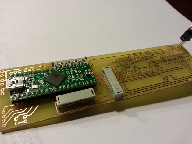
Tada! A freshly etched and drilled board, with the main components plugged in.
Toner Transfer
One of the toughest things was to find some proper way to protect the copper on the board from the etching material. I tried printing the design on some glossy photo paper, but while trying to perform the transfer using an iron I found out the hard way that the paper contained a lot of plastics, thus ending up with a piece of paper glued to my iron. 😛 Then I found an ingenious bloke on the Internet that used cheap advertising folders and papers to do the transfer. This paper is awesome because you can get it for free and people even bring it to you for free! 😛 Also it is very thin and easy to feel off with the help of a little warm water. Only printing on the paper was a little harder, the paper is so thin that my laser printer couldn’t really get a grip and started munching the paper. After some tries I just taped the cheap paper to a piece of normal printing paper and everything came out clean.
The idea with PCB design toner transfer is that the laser printer toner is based on a kind of plastic that melts at higher temperatures. Thus printing it on a paper and then ironing it to a copper board will transfer the plastic toner to the copper board, hence the name “Toner Transfer”. Awesome! … so, now what?
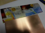
The design on the cheap paper
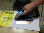
Ironing the paper to perform the toner transfer
Etching
After having the design ironed on the board, getting the copper etched off is fairly simple. I just used a commonly used Ferricchloride solution and bathed the copper board in there for about 10 minutes. After that time I ended up with a nice little board, but with the printer toner still on. Nothing that a little thinner can’t handle 😉
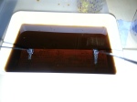
The board in the etching solution
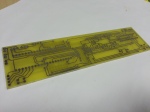
The freshly etched board
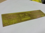
After a little thinner the copper traces are clearly visible
Drilling
Aargh, etching the board was the fun part! Having to drill the 226 holes for the components and vias (a pathway from the top of the board to the bottom of the board) was a pain. Also while drilling I discovered that the top and bottom traces were slightly misaligned. So here and there I might run into some problems while soldering, but we’ll deal with that later. If it’s really a problem I might just have some company develop the board for me, because drilling was quite a lengthy job and simply a bore. Plus if you let someone else develop your board you only have to worry about soldering on your components, now I have to solder all the vias myself and I don’t have the nice green solder-stop protective coating. However, below is the etched board with some of the main components already in place. Tonight I will start on soldering all the components and quite possibly also be able to test the buttons and leds.
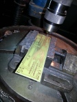
Drilling the 226 holes. Fun…
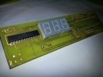
Bottom layer with the led digits and the max7219 chip to control the leds and digits
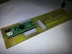
The top-side with the teensy, the connectors and the power regulator
 FCBInfinity GitHub updates


Recent Comments