mackatackblog

Behringer FCB1010 mods and more!

FCBInfinity: Stompbox modes explained

Since I frequently get questions about this I think it’s time I explained little better what I have in mind with the “Stompbox modes” I had announced.
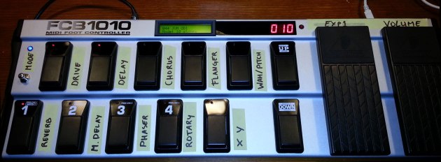
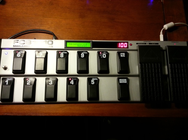
I’ve added (cheap, temporary) stickers to indicate which button controls which effect on the AxeFx

Seeing the image above you can clearly see that I intend to have every button control an effect. This is accomplished by toggling the bypass state of the associated effectblock on the AxeFx, by sending a ControlChange message via MIDI.

The metal button on the left is the ‘Mode Switcher’. With this button I can loop through the various modes described below:

10-stomps mode

That’s the mode you can clearly see in the image above and, like explained, in this mode every button controls an effect. The old bank buttons ‘UP’ and ‘DOWN’ now recall the next or previous preset on the AxeFx. So in this mode you can still move to a nearby preset quite easily without tap-dancing back and forth through the different modes 😉 The X/Y button sets all the effect blocks to either X or Y state. So even this nice feature of the AxeFx lies at your finger… err.. toe tips.

‘Normal’ mode

With one press on the mode selector we loop back to the ‘Normal’ mode. I call this the normal mode because this is how my FCB1010 was originally setup with the old UnO chip. One row stomps, one row preset selectors and BankUp and BankDown selecting banks on the FCB. This is all the same with the exception of the X/Y button. So in this mode you don’t have 5 preset selectors as you would normally have, but 4 and the X/Y toggle. This mode is still nice if you have a couple of different presets you use throughout a song.

Looper mode

Keeping the mode switcher pressed for 2 seconds will move us to the Looper mode, where all the buttons will magically transform into controls for the Looper in the AxeFx. (which at this time is not yet programmed into the FCBInfinity yet, but is really easy to implement). The looper is a nice little feature where you can play and record something you play into the AxeFx and keep looping it, so you can solo over it or add some layers to your song, quite nice.

No constrains

That’s about it on the modes. I just want to stress that this is my setup and I don’t want to force you to use the FCBInfinity like I do. The source code is completely open, you can even modify the PCB if you wish. Should you want three banks of 10 effect stomp buttons, that’s only 5 minutes worth of programming time. Like it says, the FCBInfinity gives you infinite possibilities. It could also control other devices; one stomp-mode could control the AxeFx, another mode could play chords on a keyboard! Have fun, you’re free to do anything! 😛

Current status:

A little bit more on the current progress; as said I still have to implement the looper mode, which should take no longer than 30 minutes now I have all the right software tools at hand. All that remains is adding the tap-tempo button, the tuner button, a reset button on the back of the device for easier programming of the Teensy chip, some finishing touches of the backpanel (usb port for programming). After that it’s all done. Then it’s time to create some permanent labels that have room to show what the button will do in the various modes.

Behringer FCB1010: FCBInfinity finally doing what was intended!

… it’s working! Haha, it’s 1:30 am here, and tomorrow I will probably read this post and see many typos but nonetheless I wanted to share the following with you:

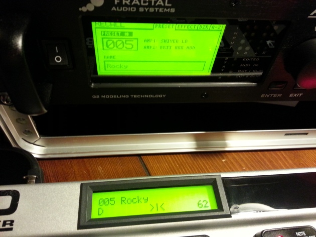
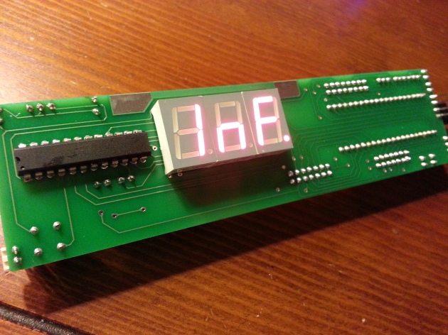
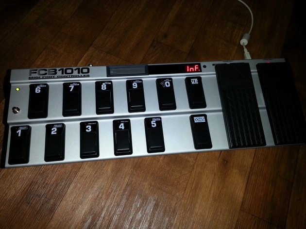
Nais! We’ve got patch names and tuner on the display over midi!

Really awesome! I also found out that the AxeFx (at least the AxeFx-II) sends a midi message when you change presets manually on the AxeFx, this means I can keep the FCBInfinity totally in sync. So far I can request the AxeFx to send the patch name and display the response on-screen and also display the Tuner messages. Unfortunately the AxeFx doesn’t send tuner messages all the time and you really need to enable the tuner (by Midi) on the AxeFx to receive the tuner data. That means I do need to add a dedicated button to toggle the tuner.

The 1 to 10 buttons on the FCB are programmed to change between patches 1 – 10 on the Axe at the moment. I only have one strange thing when sending the ProgramChange messages to the AxeFx. Changing presets from 1 – 10 work fine, except when I change to preset #2, then the Axe suddenly jumps to 384 (Bypass). Changing to patch #1 and #3 work fine… Mind boggling, someone got a clue?

Anyways, now I have most of the components I need to make this into a kick ass controller, I only have  to write the code to get the parameters for global effect blocks, so I can detect what effects are enabled/disabled on a preset change event. Exciting times!


This is what it looks like so far

A greeting to my friends at the Fractal Audio Forums


Behringer FCB1010: FCBInfinity picking up speed

Finally starting to make some big steps. I have everything soldered onto the new PCB and instead of soldering wires directly to the board it now has nice connectors, so I can connect stuff step by step. That allowed me to start putting the unit back together, so yesterday evening I had the new PCB in it’s final location and some of the optics hooked up. Unfortunately I had to order a new LCD, because a couple soldering pads got destroyed while trying to desolder the old (buggy) connector I had placed on it. It will probably arrive on monday. Fortunately I can continue development by implementing the basic MIDI stuff, I dont need the LCD for that (yet).

Everything soldered onto the new PCB

The bottom side of the new PCB

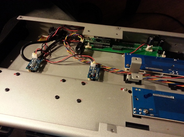
The location of the new PCB in the unit. This clearly shows why you need to remove the power supply and use a phantom power mod.


Below you can see the LED digits are working. The Green and Blue channel of the RGB-led on the left (the stompbox bank indicator) are now controlled by the expression pedals for testing purposes.

FCBInfinity, hello world!


Behringer FCB1010: PCB Bliss

Sorry for not updating a while, but here’s what happened in the meanwhile:

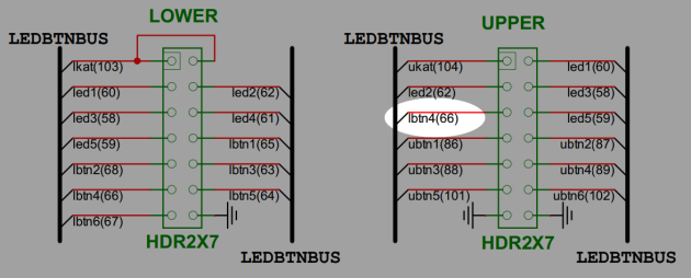
The DIY printed circuit board I created myself had some errors that I tried to fix by cutting some traces on the board and soldering new wires to replace the traces, while this worked it didn’t really feel dependable anymore. As I promised myself before, this thing should be tough and dependable. Though for testing I figured it should suffice and I could just order some nice manufactured PCBs in the meanwhile. Then I discovered another mistake in the design, as shown in the picture below I wired the connector for the upper button/led panel wrong. Led1, Led2, Led3, lbtn4, Led5, is not how the connector is wired 😛 Analysing the impact of this error led me to discarding my DIY-board alltogether, since it required me to reroute too many traces.

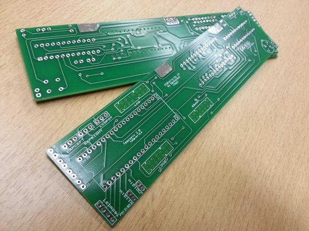
The reason I’m posting now is that the manufactured boards have finally arrived. Well, “finally”, because 1 week is blazingly fast in my honest opinion (props to www.eurocircuits.com). Yesterday I prepared a little bit by desoldering all the components from the old board, so tonight I can spend by soldering everything onto the new board. As you can see I ordered some extra boards, so once I’m done programming everything I will make those available to anyone interested (price yet to be decided). I’ve already updated everything on my FCBInfinity GitHub repository so you can make a PCB yourself or have one made for you by a PCB service. Everything will be open source, the source code as well, so you too can do anything you want with this device.

The shiny new PCBs manufactured by http://www.eurocircuits.com

Behringer FCB1010: Custom PCB update

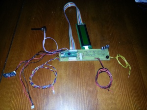
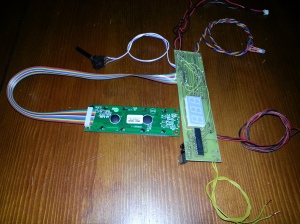
Well, it shows this is the first time I do a project like this; things don’t go as fast as I want them to. While the board turned out fine for most parts, it seems I have made two errors in the design. The first is that the power regulator is backwards. The side that needs cooling and is bolted to the exterior of the FCB1010 is now faced inward (oops). The second error is that the expression pedals require an analog pin on the Teensy, due to a last-minute change in the design it seems they are hooked to a standard digital port at the moment. To remedy these two errors I unfortunately had to cut some traces on the board and relay the traces using some wires. Not really the way I wanted the board to end up, but I guess I will just finish it all up as-is. Of course I will fix the design and I’ll just have someone develop the new board for me (or more if you’re interested in a PCB of your own). Once I receive that board I will desolder everything and move it into the corrected PCB.

Howeverrrrr… most things work great now! The LCD, the RGB-led stompbox bank indicator, the Expression pedal circuitry, the LED digits, etc, etc, they all work! Now I just have to hook the two original button PCBs up to my board and start placing everything back in the FCB1010’s housing. Then I finally can start working on programming everything the way I want them to work. Soon, soon! 😛

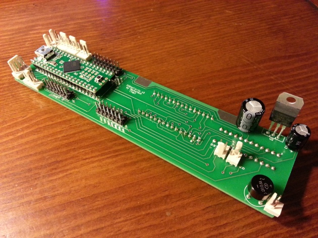
Top side of the PCB, looking good

Bottom side, clearly shows the wires I had to use to fix my errors in the design

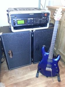
My new rack (so far)

Two days ago I have received my new bag of goodies all the way from America, through Germany to my little appartement in Holland. I must say the AxeFx in combo with the AtomicAmp cabs sound unbelievable. Mind == Blown, for sure. I wanted to let you folks know that tonight I will continue on the FCB1010 modification and quite possibly finish the soldering, drilling, hacking and sawing phase, so I can finally start on programming. Now I finally have the AxeFx (after a two month waitlist) I can finally start testing the Midi communications. Once I get the tuner on the LCD I’ll update here immediately 😉

My new setup

Behringer FCB1010: A fresh PCB!

Yesterday evening I finally got around to make a PCB. After making a testing etch I have found what would be the best method for me to approach this.

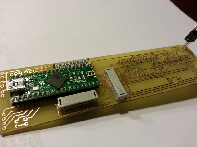
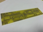
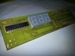
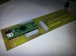
Tada! A freshly etched and drilled board, with the main components plugged in.

Toner Transfer

One of the toughest things was to find some proper way to protect the copper on the board from the etching material. I tried printing the design on some glossy photo paper, but while trying to perform the transfer using an iron I found out the hard way that the paper contained a lot of plastics, thus ending up with a piece of paper glued to my iron. 😛 Then I found an ingenious bloke on the Internet that used cheap advertising folders and papers to do the transfer. This paper is awesome because you can get it for free and people even bring it to you for free! 😛 Also it is very thin and easy to feel off with the help of a little warm water. Only printing on the paper was a little harder, the paper is so thin that my laser printer couldn’t really get a grip and started munching the paper. After some tries I just taped the cheap paper to a piece of normal printing paper and everything came out clean.

The idea with PCB design toner transfer is that the laser printer toner is based on a kind of plastic that melts at higher temperatures. Thus printing it on a paper and then ironing it to a copper board will transfer the plastic toner to the copper board, hence the name “Toner Transfer”. Awesome! … so, now what?

The design on the cheap paper

Ironing the paper to perform the toner transfer

Etching

After having the design ironed on the board, getting the copper etched off is fairly simple. I just used a commonly used Ferricchloride solution and bathed the copper board in there for about 10 minutes. After that time I ended up with a nice little board, but with the printer toner still on. Nothing that a little thinner can’t handle 😉

The board in the etching solution

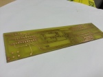
The freshly etched board

After a little thinner the copper traces are clearly visible

Drilling

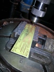
Aargh, etching the board was the fun part! Having to drill the 226 holes for the components and vias (a pathway from the top of the board to the bottom of the board) was a pain. Also while drilling I discovered that the top and bottom traces were slightly misaligned. So here and there I might run into some problems while soldering, but we’ll deal with that later. If it’s really a problem I might just have some company develop the board for me, because drilling was quite a lengthy job and simply a bore. Plus if you let someone else develop your board you only have to worry about soldering on your components, now I have to solder all the vias myself and I don’t have the nice green solder-stop protective coating. However, below is the etched board with some of the main components already in place. Tonight I will start on soldering all the components and quite possibly also be able to test the buttons and leds.

Drilling the 226 holes. Fun…

Bottom layer with the led digits and the max7219 chip to control the leds and digits

The top-side with the teensy, the connectors and the power regulator

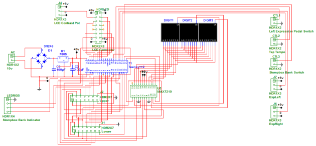
Schematic v2

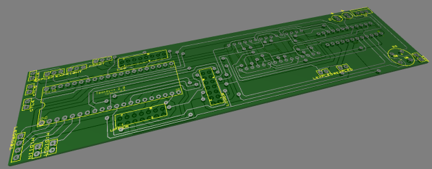
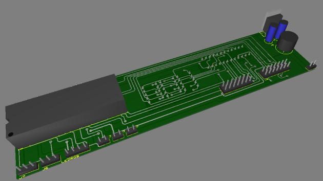
As promised I just redid the schematic for easier readability. I have also redesigned the PCB and added all the pins for the leds, buttons and other IO that isn’t mounted directly on the PCB. A new 3D shot of the PCB below. The new schematic can be viewed below, i’ve also added the PCB toner transfer for those who want to recreate this.

Tomorrow I’ll try to do the toner transfer to a copper board, IF I find some usable laser printer photo paper. I really want to finish up asap, because my AxeFx will arrive coming week (happy, happy!) 😛


EDIT: In the meantime this design has become obsolete. You can find all the recent schematics and renderings on GitHub/FCBInfinity.

FCBInfinity v2.0 Schematic

FCBInfinity v2.0 PCB Toner Transfer

Behringer FCB1010: schematics, making a mess

Well…

There’s always a first time for everything. This is the first time I’m working with PCB designing software. So far I have copied everything on my breadboard to a schematic and had the program figure out a PCB for me. I’ll probably have to redo the entire schematic from scratch because as you can see; it’s a mess, HAHA! But I have now learned how to use the program properly so the next design will be much cleaner, I promise 😛 After I get back in 2 weeks I’ll quickly redo the design and etch the copper PCB. Hopefully things will pick up speed then.

EDIT: In the meantime this design has become obsolete. You can find all the recent schematics and renderings on GitHub/FCBInfinity.

At first glance, a nice little PCB

Which came from this messy schematic, haha

Behringer FCB1010 Exterior update

I wanted to work a little bit more on the exterior, since that’s what my friends and family can easily understand. Therefore, above you can see the LCD mounted in the FCB1010’s housing. I will keep the location and looks of the bank number indicator led digits. Internally of course those will be mounted on my custom PCB. I took the original faceplate for the old led panel and bank number led digits and cut it so the LCD faceplate would fit. Since there was text and holes for the leds I have just sanded those off the backside of the platic plate. After sanding off those texts I just spray painted the backside black and that left me with a nice glossy black front panel with only the red transparent area intact for the led digits.

For those who noticed: on the left side you can see an extra push button and indicator led. That led actually is an RGB led and will be used to navigate through 3 stompbox banks. So instead of 5 stomp buttons I’ll have 15. It’s a little bit more tap dancing, but it’s only for the rarely used exotic effects.

The extra pushbutton underneath the expression pedals has already been mounted. I plan on using the right pedal for effect controls such as wah and whammy etc, the left pedal probably will be volume only, so I haven’t added a push button there yet.

Once I have everything programmed in a few weeks I plan on also adding custom button plates, to indicate which button operates which effect. I might also change the “1” button to “X/Y” select on the AxeFX and have 4 presets per bank on the FCB. Choices, choices 😛

Unfortunately my next update will probably be in about two weeks since I will be going on a holiday (poor me) 😛 I might upload a raw version of the PCB schematics before I leave though.