mackatackblog

Behringer FCB1010 mods and more!

Category Archives: Uncategorized

Behringer FCB1010: A fresh PCB!

Yesterday evening I finally got around to make a PCB. After making a testing etch I have found what would be the best method for me to approach this.

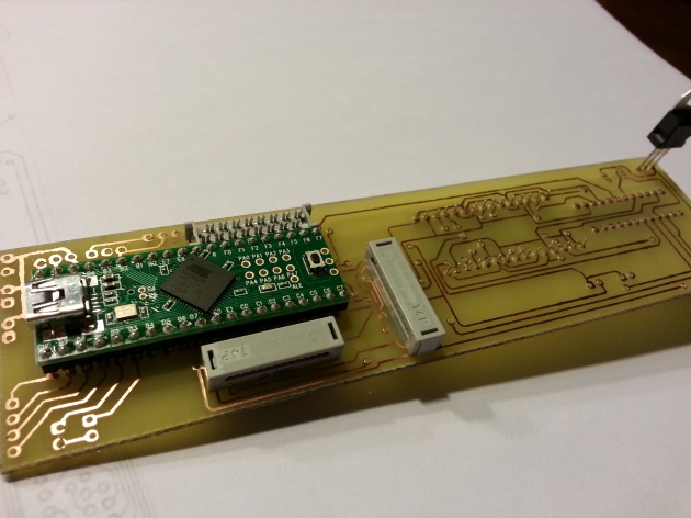
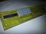
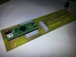
Tada! A freshly etched and drilled board, with the main components plugged in.

Toner Transfer

One of the toughest things was to find some proper way to protect the copper on the board from the etching material. I tried printing the design on some glossy photo paper, but while trying to perform the transfer using an iron I found out the hard way that the paper contained a lot of plastics, thus ending up with a piece of paper glued to my iron. 😛 Then I found an ingenious bloke on the Internet that used cheap advertising folders and papers to do the transfer. This paper is awesome because you can get it for free and people even bring it to you for free! 😛 Also it is very thin and easy to feel off with the help of a little warm water. Only printing on the paper was a little harder, the paper is so thin that my laser printer couldn’t really get a grip and started munching the paper. After some tries I just taped the cheap paper to a piece of normal printing paper and everything came out clean.

The idea with PCB design toner transfer is that the laser printer toner is based on a kind of plastic that melts at higher temperatures. Thus printing it on a paper and then ironing it to a copper board will transfer the plastic toner to the copper board, hence the name “Toner Transfer”. Awesome! … so, now what?

The design on the cheap paper

Ironing the paper to perform the toner transfer

Etching

After having the design ironed on the board, getting the copper etched off is fairly simple. I just used a commonly used Ferricchloride solution and bathed the copper board in there for about 10 minutes. After that time I ended up with a nice little board, but with the printer toner still on. Nothing that a little thinner can’t handle 😉

The board in the etching solution

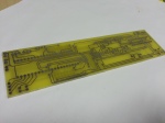
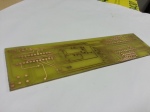
The freshly etched board

After a little thinner the copper traces are clearly visible

Drilling

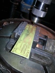
Aargh, etching the board was the fun part! Having to drill the 226 holes for the components and vias (a pathway from the top of the board to the bottom of the board) was a pain. Also while drilling I discovered that the top and bottom traces were slightly misaligned. So here and there I might run into some problems while soldering, but we’ll deal with that later. If it’s really a problem I might just have some company develop the board for me, because drilling was quite a lengthy job and simply a bore. Plus if you let someone else develop your board you only have to worry about soldering on your components, now I have to solder all the vias myself and I don’t have the nice green solder-stop protective coating. However, below is the etched board with some of the main components already in place. Tonight I will start on soldering all the components and quite possibly also be able to test the buttons and leds.

Drilling the 226 holes. Fun…

Bottom layer with the led digits and the max7219 chip to control the leds and digits

The top-side with the teensy, the connectors and the power regulator

Schematic v2

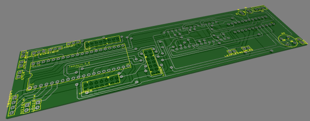
As promised I just redid the schematic for easier readability. I have also redesigned the PCB and added all the pins for the leds, buttons and other IO that isn’t mounted directly on the PCB. A new 3D shot of the PCB below. The new schematic can be viewed below, i’ve also added the PCB toner transfer for those who want to recreate this.

Tomorrow I’ll try to do the toner transfer to a copper board, IF I find some usable laser printer photo paper. I really want to finish up asap, because my AxeFx will arrive coming week (happy, happy!) 😛


EDIT: In the meantime this design has become obsolete. You can find all the recent schematics and renderings on GitHub/FCBInfinity.

FCBInfinity v2.0 Schematic

FCBInfinity v2.0 PCB Toner Transfer

Behringer FCB1010 Exterior update

I wanted to work a little bit more on the exterior, since that’s what my friends and family can easily understand. Therefore, above you can see the LCD mounted in the FCB1010’s housing. I will keep the location and looks of the bank number indicator led digits. Internally of course those will be mounted on my custom PCB. I took the original faceplate for the old led panel and bank number led digits and cut it so the LCD faceplate would fit. Since there was text and holes for the leds I have just sanded those off the backside of the platic plate. After sanding off those texts I just spray painted the backside black and that left me with a nice glossy black front panel with only the red transparent area intact for the led digits.

For those who noticed: on the left side you can see an extra push button and indicator led. That led actually is an RGB led and will be used to navigate through 3 stompbox banks. So instead of 5 stomp buttons I’ll have 15. It’s a little bit more tap dancing, but it’s only for the rarely used exotic effects.

The extra pushbutton underneath the expression pedals has already been mounted. I plan on using the right pedal for effect controls such as wah and whammy etc, the left pedal probably will be volume only, so I haven’t added a push button there yet.

Once I have everything programmed in a few weeks I plan on also adding custom button plates, to indicate which button operates which effect. I might also change the “1” button to “X/Y” select on the AxeFX and have 4 presets per bank on the FCB. Choices, choices 😛

Unfortunately my next update will probably be in about two weeks since I will be going on a holiday (poor me) 😛 I might upload a raw version of the PCB schematics before I leave though.

Behringer FCB1010 LCD update

FCB1010 on a breadboard with LCD (click for larger image)

A little big update on the Behringer FCB1010 LCD project. I wanted to show you guys and gals that I’m progressing quite nicely. As you can see from the picture i took out all the internals of the fcb and hooked them all up to a Teensy++ on my breadboard. Im using a MAX7219 IC to control all indicator leds and led digits with just three pins on the Teensy board. Midi in/out is also done.

Theoretically you could internally just hook the original Midi OUT to the Midi in on my breadboard Midi In and use the Midi Out from the breadboard as new Midi Out. That way you could leave the entire FCB in tact, only redirect two wires from the Midi In/Out PCB to and from the Teensy and you’re all done. Using that little change one should be able to show AxeFX patch names and tuner info on the LCD. Adding two buttons for tuner enable/disable and tap tempo should be peanuts then. Once my AxeFX arrives and I get to test everything i will make sure to post the source code for the Teensyduino / Arduino IDE.

As i have announced i would probably let the Teensy handle all the IO. I have decided to take that road, so that’s why the setup in the picture looks a little more complicated, as it already has the FCB1010’s button and led PCB’s connected. I plan on adding a RGB led, three push buttons and a button under the expression pedals, so they can be switched on/off by pushing the pedal down a little further. The RGB-led will be an indicator on which stompbutton bank is selected (more info about this in a future post). As seen in the picture on the LCD: FCB-Infinity is alive! 😛

Next up: designing the custom PCB to replace the breadboard. This thing needs to withstand life on the road, so no shortcuts there.

Behringer FCB1010 Power and Midi IN/OUT over single UTP / RJ45 Cable Modification

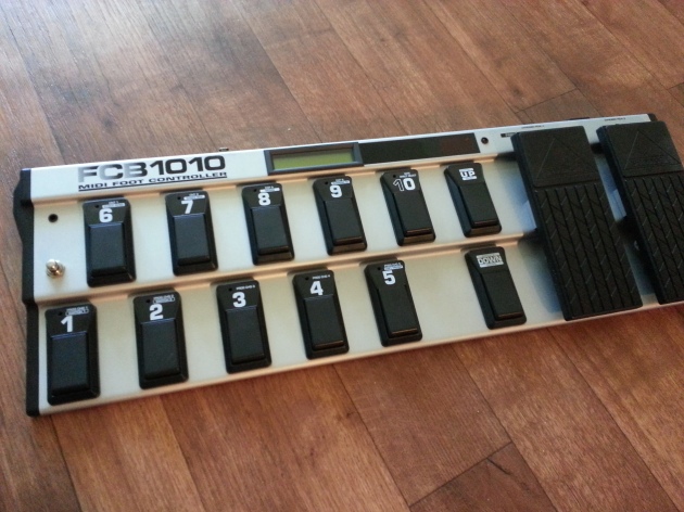
After seeing many nice modifications for the popular Behringer FCB1010 MIDI pedal board I have decided to create one of my own. Unable to find information for a mod with similar cabling i decided to post my findings here. Just to inspire others to create even better mods for this awesome pedal board.

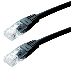
The main purpose of this mod is to provide the FCB with a single cable for two-way Midi and power. I don’t want a million cables on the floor and I was looking for a cable setup that was cheap and the cable should be easily replaceable. I need 4 conductors for Midi and 2 for power, therefore I decided to go for a simple computer UTP cable which has 8 conductors. These cables are cheap and easy to obtain and they come prefab in many different lengths and colors.

There are quite a few phantom power mods out there which require one to use either switches or diode-rectifiers to switch between phantom- or self-powered operation of the FCB. I decided I would never want to have the FCB self-powered and I would just take the power converter from the board. This would make the setup much simpler.
Materials for this project:

(all bought from conrad.nl for those in Europe)

1x Euro-casing black 150x50x80mm (part# 520616)

€ 2,85

2x Neutrik RJ45 chassis bus NE 8 FDV (part# 746738)

€ 12,54

1x CAT 5E cable F/UTP 5m (part# 990581)

€ 13,99

1x 3m 5pin midi cable I had laying around

€ 6,79

Tapered drill
Some shrink tubing
Soldering supplies and tools
Total

€ 36,17

(€ 36,17 is roughly 45 USD)

Ripping out the power converter

As mentioned earlier I decided to use the FCB1010’s own power converter and relocate it into to an external casing for phantom power. So first step was to clip the wires on the power converter and take it out of the FCB. Make sure to clip the yellow wires, leading to the circuit board, halfway so you can have enough room to solder the clipped ends to the RJ45 connectors later on. Removing the power converter looks easier said than done. In the end I had to push out the main power switch and temporarily remove a glued led before I was able to do so.

Be safe and properly seal the wires from the old main power connector, so you don’t get electrocuted when someone accidentally hooks up a power cable to the old connector.

Relocating the power converter to its new home

The power converter in my unit has three input wires and two output wires (as seen below). But like the original setup I only used the red and black input wires. Since this casing would be permanently installed in my flight case I opted to just make direct cables for the connections that would stay connected permanently: Power to my power conditioner and Midi to my AxeFX. Therefore I just soldered a power cable directly to the two input wires of the power converter.

The two yellow output wires from the power converter are also alternating current (AC). Since the current alternates we don’t have to worry about positive and negative and we can just solder the two wires to two of the pins on the RJ45 chassis bus. I used shrink tubing to tidy everything up.

Midi in the external case

After I made two holes for the midi cables I cut the 3 meter midi cable in pieces so that I ended up with two midi connectors and a piece of wire of the length I desired. After stripping the wires I soldered the 4 and 5 pin wires to 4 pins on the RJ45 chassis bus. Notice how I made a knot in the power and midi cables, preventing tension on the soldering if one would pull on those cables.

A few tips on soldering: 1/ If you want to use shrink tubing, put over the wire before soldering 😉
2/ Pre solder some tin on the wire and pins before making the actual solder, this gives you a free hand to hold the wires in place.

Drilling the FCB1010

As seen in the photo below I located the RJ45 bus next to the external switch jacks. This location gives you a lot of room to solder your wires and still be close to the midi connectors on the FCB. Disconnect the plug for the external switch 1&2 from the FCB circuit board to give yourself a little more room to operate.

Drilling the hole for the bus proved to be the hardest part of the project. After destroying a few of my Dremel bits I decided to get a tapered drill to finish the job. That was really the easiest way to get the hole to the size I wanted.

A tapered drill

Soldering the FCB RJ45

Remember we cut the yellow power wires in half at the start of the project when we took out the power converter? Now we should have more than enough wire to reach the RJ45 bus. Find the pins you used for the power and solder the yellow wires to them. Again, it’s alternating current, so order doesn’t matter. Don’t forget your shrink tubing.

Next up is the soldering of the Midi wires. We’re just going to solder the wires from the RJ45 bus to the original midi input and outputs of the FCB. At this moment it doesn’t really matter what pair we solder to which midi port, just as long as you solder the pairs to the 4 and 5 pins. On the connectors it’s the pin 2 and 4 counted from left to right, or another way to describe: don’t solder on the middle and outer pins. 😉 Keep in mind that unlike the power cables, the Midi is directed so polarity does matter. In my case I had to de-solder the wires from the original midi connectors and swap them, because the FCB wouldn’t work.


Don’t forget to reconnect your external switch 1&2 connector if you want to use them.

The end (result)

The end result is that I have a tidy little box that I can just leave permanently connected in my flight case and when I want to hook up my FCB I just have a single cable to plug in.

I think my next project is to add a LCD and a couple of extra switches to the FCB using a Teensy development board and have the Teensy board also communicate over Midi. This would allow me to show the AxeFX tuner and patch names on the FCB. I might go crazy and completely gut the FCB and have the Teensy handle all the buttons. End result: (midi) world domination, but then this would no longer be a FCB1010, but FCB-Infinity or whatever. I’ll make sure to split up those projects in two steps, so I can show you how to have the FCB communicate with AxeFX with minimal changes to the FCB.

I hope you enjoyed!